Introduction: Why the CNC Workflow Matters
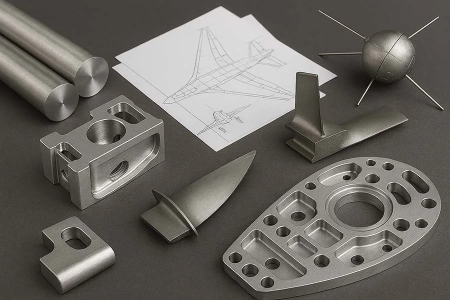
If you’ve ever watched a CNC machine carve a raw block of metal into a shiny, precision-made part, you know it feels a little like magic. But in reality, the process is a carefully designed workflow — from the first CAD sketch to the final finished part.
A strong CNC workflow is not just about speed. It’s about accuracy, repeatability, and efficiency. Done right, CNC can save companies millions. Done poorly, it can cost hours in rework, tool wear, and material waste.
In this article, we’ll break down the CNC workflow step by step, explore its advantages and pitfalls, and answer the most common questions people ask about it. Whether you’re an engineer, machinist, or just curious about how your smartphone case or car engine block comes to life, this guide has you covered.
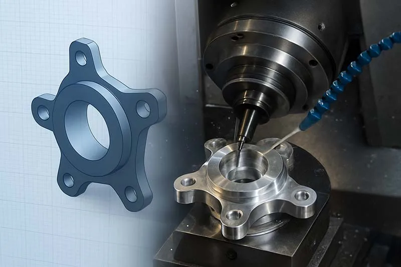
Step 1: CAD (Computer-Aided Design) – The Blueprint
Every CNC journey begins with CAD software like SolidWorks, Fusion 360, or AutoCAD. Engineers create a 3D model of the part, including dimensions, tolerances, and sometimes materials.
Key features of CAD stage:
- Precise geometry and dimensions
- Digital prototypes reduce errors before production
- Allows simulation of stresses, fits, and assemblies
⚠️ Critical Note: Not all CAD models are CNC-friendly. Overly complex geometries or missing tolerances can create huge headaches downstream.
Step 2: CAM (Computer-Aided Manufacturing) – The Strategy
Once the design is ready, it goes into CAM software (e.g., Mastercam, Fusion 360 CAM, Edgecam). This is where machining strategies are planned:
- Toolpaths: defining how cutting tools move
- Speeds & Feeds: optimizing cutting parameters
- Simulation: checking for collisions and tool wear
Technical detail: Toolpath optimization can reduce machining time by up to 40% while extending tool life.
⚠️ Bad side: Poor CAM programming often leads to wasted material, broken tools, or excessive cycle times.
Step 3: Post-Processing – Speaking CNC’s Language
CAM produces G-code, the universal CNC machine language. But machines differ, so post-processors translate generic toolpaths into machine-specific instructions.
Example: A Haas CNC might need a slightly different G-code than a Mazak or DMG Mori.
Step 4: CNC Machining – Where Metal Meets Machine
Now comes the fun part. The machine takes the G-code and executes it. Depending on the part, this might involve:
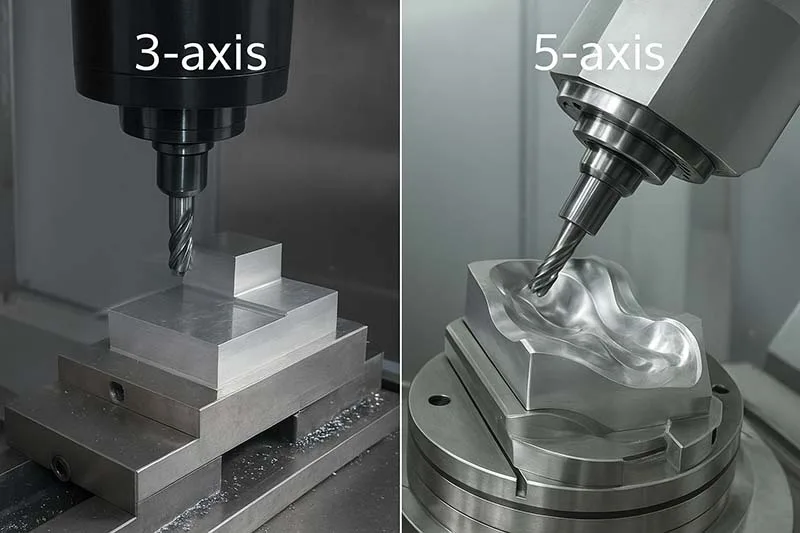
- Milling (3-, 4-, or 5-axis)
- Turning (lathes)
- EDM (Electrical Discharge Machining)
- Hybrid methods (additive + subtractive)
Specs worth noting:
- Accuracy can reach ±0.001 mm on high-end machines
- Surface finishes as smooth as Ra 0.2 µm
⚠️ Reality check: Not every shop has cutting-edge machines. Entry-level CNCs can struggle with tight tolerances or exotic materials.
Step 5: Inspection & Quality Control – The Final Judge
Before shipping, parts undergo inspection:
- CMM (Coordinate Measuring Machine) scans parts for tolerance compliance
- Surface roughness tests ensure proper finishes
- Non-destructive testing for aerospace or medical parts
Poor inspection routines can mean rejected parts, warranty claims, and unhappy customers.
Step 6: Finishing – The Last Touch
Some parts require extra finishing:
- Deburring
- Polishing
- Heat treatment
- Coating (anodizing, plating, powder coating)
Interesting Fact: Aerospace turbine blades often spend longer in finishing than in CNC machining due to the extreme quality demands.
CNC Workflow at a Glance (Simplified)
- CAD → Design the part
- CAM → Plan the machining
- Post-processing → Convert to G-code
- Machining → CNC executes toolpaths
- Inspection → Verify tolerances
- Finishing → Final surface prep
Pros and Cons of the CNC Workflow
✅ Pros:
- High precision and repeatability
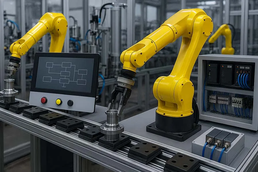
- Automated for speed and efficiency
- Wide material compatibility
❌ Cons:
- High setup costs (machines + software)
- Steep learning curve in CAD/CAM
- Poor designs = wasted production time
Lesser-Known Facts about CNC Workflow
🔹 Lesser-known Fact 1: NASA once machined space shuttle tiles with CNC but had to add hand-finishing because the CNC tolerances were too perfect — the tiles wouldn’t fit due to thermal expansion gaps.
🔹 Lesser-known Fact 2: Some industries intentionally design tool wear into the workflow — knowing a tool will dull at a specific point helps predict maintenance and avoid unexpected downtime.
CNC Workflow: From CAD to Finished Part FAQ
Want To Read More?
- CNC Machining Processes & Technologies
- CNC Workflow: From CAD to Finished Part
- Tooling and Fixtures in CNC
- Multi-Axis Machining: 3-Axis vs 5-Axis
- AI and Machine Learning in CNC: The Future of Smart Manufacturing
- Predictive Maintenance and IoT in CNC
- Digital Twins in CNC Systems
Conclusion: From Digital Sketch to Reality
The CNC workflow is the bridge between imagination and reality. From CAD design to post-processing, machining, and inspection, every step plays a vital role in delivering a finished part that meets modern industry standards.
Yet, the process isn’t perfect. CAD errors, poor CAM programming, or weak inspection routines can derail production. Still, when executed well, CNC remains one of the most powerful and efficient ways to turn raw material into high-performance products.
💬 Your Turn: Have you worked with CNC workflow in your shop or projects? What’s the biggest challenge you’ve faced — CAD issues, CAM programming, or machine setup? Share your thoughts in the comments below and pass this guide along on social media to help others master CNC!